
Updated 2012/04/12: This is an old page. It persists on this site for posterity, but the information presented below is no longer up-to-date. When you are done here, then please click forward to this page, which describes how to control refraction errors with limiters on the spectral propagation velocities.
Updated 2011/08/30: Added a link to Part 2.
Updated 2010/02/11: Added refraction as a nodal attribute.
At the end of my instruction manual on how to compile and run SWAN+ADCIRC, I noted that wave refraction can cause problems in regions where the resolution of the bathymetry is insufficient. We worked around this problem by turning off the refraction on the local sub-meshes that were not in our region of interest. On this page, I will provide more description of exactly what can go wrong when waves are allowed to refract on coarse meshes, and I will share more details about our work-around.
It should be noted that wave refraction will always be a problem whenever any wave model is applied on a coarse mesh. This is a general numerical problem whenever the user is trying to compute waves turning over more than 90° in one spatial step. This would be a problem with SWAN, WAM, STWAVE or any other wave model, regardless of if/how they are coupled to a circulation model. As we will see, it is the coarse mesh that causes problems with wave refraction.
Motivation
Wave refraction is essential. According to Holthuijsen (2007),
The phenomenon of the wave direction changing due to depth-induced variations in the phase speed in the lateral direction (i.e., along the wave crest) is called refraction. It turns the wave direction towards shallower water and results in either an increase or a decrease in wave height, depending on the actual changes in wave direction.
As waves enter shallower water, they try to turn so that their crests are parallel to the contours of the bathymetry. Refraction can have a dramatic effect on wave behavior nearshore, because it is one way in which the waves interact with the complex bathymetry of the continental shelf and other features near the coast. For that reason, it is enabled automatically by SWAN and other wave models. For more detail about how the wave refraction is formulated in SWAN, please see its User Manual.
The following animation shows the effects of wave refraction on the significant wave heights during a Katrina simulation on our SL15 mesh. These effects are shown as the difference between the wave heights in runs with and without wave refraction. Warm colors indicate regions where refraction has increased the wave heights, while cool colors indicate regions where refraction has decreased the wave heights.
Effect of wave refraction on significant wave heights (m) during Katrina (2005).
The brown lines on the animation are the road/levee boundaries in our SL15 mesh. This is southeast Louisiana, so New Orleans is located where the levee system is most dense. The levees extend southeastward from New Orleans along the Mississippi River. Katrina will make its first landfall along those river levees, track northward over Caernarvon Marsh and Lake Borgne, and then make its second landfall along the Mississippi coastline.
Note the complexities in this difference plot. As Katrina moves onto the shelf and makes landfall, the wave refraction has a dramatic effect on the significant wave heights. They are adjusted alternatively up or down, depending on the bathymetry and the wave directions in any given area. Just to the west of the bird’s foot of the Mississippi River delta (and near the geographic coordinates of -89.5° longitude and 29° latitude), the slope of the wave heights is increased, so that they are much smaller away from the coastline and much larger right at the coastline. Similar behavior is observed throughout the region, with differences ranging to 1m or more.
ADCIRC is forced partly by SWAN via the passing of radiation stress gradients, which are computed through an integration of the wave spectra, much as the significant wave heights are computed. Thus, gradients in the wave heights correlate strongly to gradients in the radiation stresses. If refraction has an effect on the wave heights computed by SWAN, then it must also have an effect on the water levels and currents computed by ADCIRC.
The following animation shows the effects of wave refraction on the water levels during a Katrina simulation on our SL15 mesh. These effects are shown as the difference between the water levels in simulations with and without wave refraction. As before, warm colors indicate regions where refraction has increased the water levels, while cool colors indicate regions where refraction has decreased the water levels.

Effect of wave refraction on water levels (m) during Katrina (2005).
It seems the wave refraction does not have as dramatic an effect on the water levels for this simulation. We see an increase in the water levels to the west of the bird’s foot of the Mississippi River delta, and we see an increase farther west, near Timbalier Bay. However, these increases are on the order of about 20cm. It is interesting that the greatest increases happen to the west, where the continental shelf is much broader. In other applications, where the shelf is broader and thus the bathymetry changes more slowly, the wave refraction may have a greater effect.
So we definitely want to include wave refraction in our computations. It is one way in which the waves interact with the bathymetry, and it can increase both wave heights and water levels.
Problem
The previous figures showed the effects of wave refraction on wave heights and water levels, by taking differences between simulations with and without refraction. Those runs were smooth and reasonable in this region near southeast Louisiana, because our SL15 mesh is highly resolved in that area. However, as noted at the top of this page, problems can arise when waves are allowed to refract on coarse meshes.
The animation below depicts the significant wave heights on our SL15 mesh as Katrina moves through the Gulf of Mexico. We can see the wave field develop in the Gulf as Katrina generates large (22m) waves in deep water, propagates them onto the continental shelf, and then breaks them nearshore due to changes in bottom friction and water depth.
Non-physical significant wave heights (m) when wave refraction is enabled everywhere during Katrina (2005).
However, that wave behavior in the northern Gulf is rivaled by extraneous wave action in the Caribbean Sea and the Atlantic Ocean. Our OWI wind forcing is only applied to the Gulf, but large waves are being generated in random places throughout the rest of the domain. These waves appear very early in the simulation and then seem to reach a dynamic equilibrium.
(It should be noted that both models remain stable throughout this simulation. SWAN is generating very large waves, which have significant heights that probably range to 50m or more, but it does not go unstable. SWAN also computes radiation stress gradients, which are closely related to the gradients in these significant wave heights, and then passes them to force the ADCIRC solution. These gradients are large in the Caribbean Sea and the Atlantic Ocean, but ADCIRC also remains stable. It is actually testament to the robustness of both SWAN and ADCIRC that they remain stable under such conditions.)
We can learn more about this spurious wave action by zooming into a region near the Bahamas:
Non-physical significant wave heights (m) near the coarsely-resolved Bahamas when wave refraction is enabled everywhere during Katrina (2005).
There are several “hot spots” of wave action in this area, even though it never receives wind forcing during the SWAN+ADCIRC simulation of Katrina. Two regions see significant wave heights larger than 21m, including one region far away from the islands in our SL15 mesh. It turns out that, in real life, a small, uninhabited island (the Samana Cays) is located in that region, but it is too small to be represented as an island boundary in our SL15 mesh.
Let’s zoom even further into that region, where the wave action is large. We will change the scale this time, to increase the maximum significant wave height from 21m to 60m. And we will now plot the computational mesh onto the figure:
Non-physical significant wave heights (m) when wave energy is refracted at a single mesh vertex during Katrina (2005).
With this scale, and with the computational mesh also plotted on the figure, it is fairly easy to see that the problem is caused at just one vertex in the mesh. The significant wave heights increase to unreasonably large values at that vertex, eventually reaching about 75m, and then that wave energy is propagated northward on the currents. To the south of the problem vertex, the wave heights decrease to near zero over the length of just one triangular element.
This behavior is caused by the wave refraction in SWAN. Small amounts of wave energy are refracting toward that one mesh vertex, because it is located at a local peak in the bathymetry. This can be seen clearly by examining the water depths in this region:
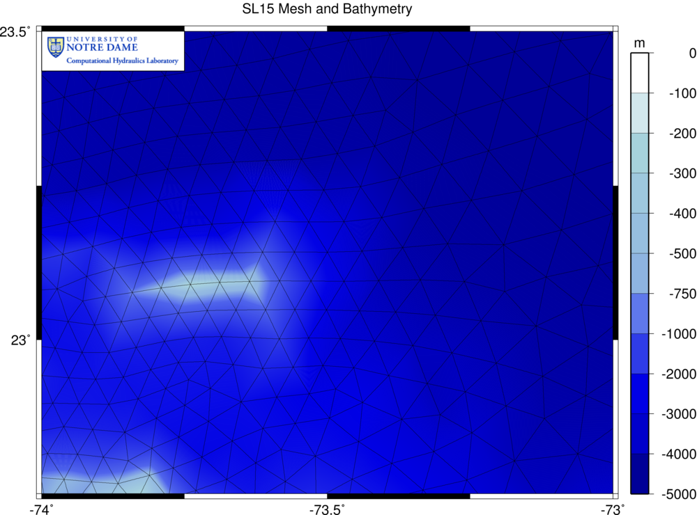
Unstructured mesh and bathymetry (m) near the coarsely-resolved Samana Cays in the Bahamas.
The small island (the Samana Cays) has been represented with three vertices in the mesh that are much more shallow than their neighbors. At those three nodes, the water depths are on the order of a few hundred meters or less, but then the depths drop off to about 1000m over the length of one triangular element. At the most shallow vertex, the depth is only 1-2m, and that is where the wave refraction is causing problems. The gradients in the bathymetry are much too large. This was never a problem when ADCIRC was run by itself, because we can compute tides and surge on this coarse mesh. But SWAN experiences problems when wave refraction is activated. Any other wave model would experience similar problems.
Note that, overall, the SL15 mesh is actually a highly-resolved mesh for hurricane storm surge simulations. We have been very successful while applying it to hindcasts of Katrina and Rita, and we have used it for a wide range of projects for the USACE, FEMA, and other national, state and local agencies. The mesh includes a detailed representation of the complex nearshore geography, channels, lakes, estuaries and other natural features that transmit and collect storm surge. But it also extends far into the Atlantic Ocean, so that boundary conditions can be applied naturally, and hurricane conditions can be developed within the computational domain. Our newer meshes will offer even higher levels of resolution, but they will be the first generation of meshes designed with SWAN in mind. ADCIRC modelers must now consider the wave field when designing meshes.
Also note that the wave refraction is exaggerated in this example because the bathymetry gradients are even steeper than normal. We are trying to model a small island with only three mesh vertices, and we are varying the bathymetry over two or three orders of magnitude. This causes the wave energy to turn toward the most shallow vertex and collect there, eventually reaching a maximum significant wave height of about 75m, as we saw above. Similar problems occur whenever there is a coarsely-resolved plateau in the bathymetry. Even if the most shallow vertex has a water depth of several hundred meters, the waves will refract toward it if the bathymetry gradients are steep to its neighbor vertices. The result is the messy, useless simulation shown in the examples above.
Solution
There are actually four possible ‘solutions’ to this problem:
- In the long term, we need to design meshes that are compatible with both SWAN and ADCIRC, as I noted above. Especially in the case of the tightly-coupled SWAN+ADCIRC, in which both model components utilize the same computational mesh, we need to design meshes that resolve the necessary features for both components. If we want waves to refract near this island, then we need to employ a mesh resolution that is finer than about 5km, which is what is employed by SL15. Instead of modeling the small island with a shallow set of three vertices, we need to add resolution along the shelf break and around the island. SWAN is a robust model, but, like any wave model, it is only as good as its inputs.
- In the short term, there are three other solutions that attempt to allow wave refraction on coarse meshes. One idea would be to develop a numerical scheme that will allow excessive wave refraction, but results will only be realistic if the water depths are correspondingly excessive. However, that is not typically the case. If the region is of any interest, then the user will probably apply an appropriate level of resolution to model the changes in water depths and allow for wave refraction. So there has not been a need for the development of such a numerical scheme.
- Another idea is to use the numerical scheme that is currently available in SWAN, where wave refraction on coarse meshes can cause problems, as shown above. SWAN will continue to compute, but its results will not be realistic in the down-wave region of the problem area. That region is usually a nearby beach or some other area in which the user is not interested, or else an appropriate level of resolution would have been applied. However, the wave will move occasionally into deeper water, and the down-wave area can become quite large.
-
Our work-around is to enable wave refraction only in the regions where we have sufficient resolution of the bathymetry. Note that it is only appropriate to disable the wave refraction after we have verified that it can be ignored in parts of the computational domain. The user should first run SWAN with refraction everywhere, and then see where it should be turned off.
We can do this by applying a slightly different set of physics on each local sub-mesh, so that each computational core runs SWAN in a slightly different way. The wave refraction is enabled by default in SWAN. We will disable the wave refraction in the global SWAN control file (
fort.26), and then we will re-enable refraction on the local sub-meshes of our choosing. We can do this by:-
Disabling the wave refraction in the global SWAN control file. By default, SWAN enables wave refraction in its simulation. We can disable most types of wave physics by using the
OFFcommand. In this case, we insert the command:OFF REFRACanywhere in the control file. This will tell SWAN that we want wave refraction to be disabled during its computations.
-
Running adcprep to decompose the mesh and copy the SWAN control file into the local PE directories. Assuming that adcprep has been compiled for use with the coupled model (as described in step 4 in “How to Compile and Run SWAN+ADCIRC”), it will prompt the user for the name of the file (
fort.26) and then copy that file into the local directories. Each compute core now has its own copy of the SWAN control file. -
Using the Fix26.f90 program to enable wave refraction in your region of interest. This program will prompt the user for a lon/lat box, inside which it will enable refraction. The program reads the local mesh (
fort.14) and SWAN control files (fort.26), and it checks to see if the local mesh is contained fully within the user-specified lon/lat box. If it is, then the program will remove theOFF REFRACline from the SWAN control file, thus enabling wave refraction on that local sub-mesh.
Updated 2010/02/11: The work-around described above is effective, but it does change the solution depending on the domain decomposition. If the mesh is decomposed over a relatively small number of cores, then relatively few of the local sub-meshes will be contained fully within the northern half of the Gulf of Mexico, and thus wave refraction will be enabled sporadically. And, obviously, a serial simulation would have to disable wave refraction everywhere. For those reasons, I have added wave refraction as a nodal attribute in the
fort.13file, as described below.Our work-around is to enable wave refraction only in the regions where we have sufficient resolution of the bathymetry. Note that it is only appropriate to disable the wave refraction after we have verified that it can be ignored in parts of the computational domain. The user should first run SWAN with refraction everywhere, and then see where it should be turned off.
We can do this by applying the wave refraction as a nodal attribute in the
fort.13file. At nodes where the wave refraction is set as zero in the nodal attributes file, SWAN will not consider it. However, wave refraction will be enabled at nodes where wave refraction is set to unity in the nodal attributes file. In this way, the same computational core could have a sub-mesh on which wave refraction is enabled and disabled in different regions. We can do this by:-
Enabling the wave refraction in the global SWAN control file. SWAN considers wave refraction by default, so there is no change to the
fort.26file. This will tell SWAN that we want wave refraction to be enabled during its computations. -
Adding the wave refraction as a nodal attribute in the
fort.13file. It is controlled by the new alphanumeric label:wave_refraction_in_swanand it is a scalar quantity (so only one value at each node). It is recommended that unity by the default value, and then the user list nodes where the non-default value of zero be applied. In this way, wave refraction will be enabled in the densest, highly-resolved regions of the mesh, and disabled elsewhere. You can use the Fix13.f90 program to add wave refraction to an existing nodal attributes file.
-
Running adcprep to decompose the mesh and copy the SWAN control file into the local PE directories. Assuming that adcprep has been compiled for use with the coupled model (as described in step 4 in “How to Compile and Run SWAN+ADCIRC“), it will prompt the user for the name of the file (
fort.26) and then copy that file into the local directories. Each compute core now has its own copy of the SWAN control file, and the newfort.13file will be decomposed onto the local sub-meshes. Then you are ready to go.
-
Disabling the wave refraction in the global SWAN control file. By default, SWAN enables wave refraction in its simulation. We can disable most types of wave physics by using the
The following image depicts a possible setting of wave refraction for this application. The default value of unity is applied throughout the northern half of the Gulf of Mexico, so that wave refraction is enabled where the highest resolution is located. But wave refraction is disabled in the rest of the domain by applying a non-default value of zero.
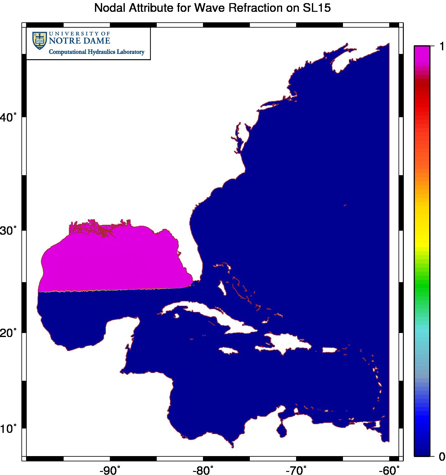
Example of enabling wave refraction only near the region of interest in the northern Gulf of Mexico.
However, it should be noted that this last method is not the preferred way for the future. As our community moves forward with coupling, be it of waves, circulation, sediment transport, etc., it will become even more important that we design our meshes to resolve all of the physical features in all of the model components. Mesh resolution that is appropriate for one model component may be too coarse for another component.
In our hurricane storm surge simulations in Texas and Louisiana, we enable refraction using the distribution shown above. The result is a much more reasonable simulation:
Significant wave heights (m) during Katrina (2005) when wave refraction is enabled only in regions with sufficient mesh resolution.
When compared with the animation above, this animation is a much better representation of the wave behavior during Katrina. Waves are generated in the deep Gulf as Katrina moves through the system, propagate onto the narrow continental shelf near the bird’s foot of the Mississippi River delta, and then break due to changes in bottom friction and water depths. Wind forcing is only applied in the Gulf of Mexico, and that is where the majority of the action is contained. When wave energy does escape the Gulf, it does not refract around shallow peaks in the bathymetry and cause problems throughout the rest of the domain.